English




Multi-material 3D printing service offers the solution to why engineers trying to find out what is PVA 3D printer filament are failing with complex parts. Combination of rigid-flex materials with deep cavities and blind holes typically causes delamination after support removal resulting in Ra > 6.3μm rough surface and mechanical weaknesses. Industry statistics indicates more than 40% of such prototypes fail functional tests despite no engineered multi-material bonding.
The following guide offers you the proven method using professional multi-material 3D printing service and precision soluble PVA support to keep tolerances ±0.05mm without washout errors. We offer you quantitative 3D printing process parameters and material selection criteria to reduce lead time up to 30% and cost per part down to 30%. Below you can see step-by-step guide on multi-material 3D printing according to LS Manufacturing engineering experience.
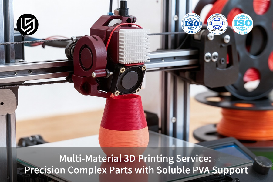
Multi-Material 3D Printing: PVA Support Quick-Reference
| PVA Support Factor | Key Requirement | Common Pitfall | Best Practice |
| Storage & Drying | Store in dry-box with <20% RH; pre-dry at 45°C for 4 hours. | Moisture causes bubbling and nozzle blockages. | Always keep with desiccant; change drying packs once a month. |
| Interface Quality | Optimize nozzle spacing; slow down during material transition. | Bad adhesion results in moving support or printing failure. | Use interface layer with 0.1mm spacing for better separation. |
| Support Design | Make hollow or grid structure to dissolve faster. | Solid supports need 12 hours+ to dissolve completely. | The optimal infill density is 30-40%. |
| Cavity Drainage | Holes should be ≥2mm and at the lowest point. | Trapped dissolved PVA slurry cannot escape. |
Place holes at all low points; check with CAD section view. |
| Hardware | IDEX dual head with purge tower. | Single head switching results in material waste and inefficiency. | Purge tower height should be ≥20mm. |
| Dissolution Process | Warm water (30-50°С) with mild agitation. | Cold water will dissolve PVA four times slower. | The water should be changed every two hours; ultrasonic bath used for internal channels. |
| Layer Height Matching | Must match PVA layer height with model material. | Layer mismatch leads to irregular support surface. | Two-layer height should be the same for both extruders. |
Key Takeaways:
- PVA is a Moisture Management Exercise: Treat PVA as if it was any other lab reagent—keep it in a dry box, pre-dry it before printing, seal it during pauses. Moisture is the biggest enemy of successful PVA 3D printing.
- Design Support for Removal: Holes or hollows are much faster to remove when using PVA supports rather than solid pieces of the same polymer.
- Plan for Drainage: Every enclosed space contacting the PVA support requires a drain hole (minimum 2mm) to avoid slurry trapping.
- IDEX Systems Excel Here: Dual independent extruders with purge towers significantly reduce the cost of print setup, as switching materials frequently takes up lots of time.
Why Trust This Guide? Practical Experience From LS Manufacturing Experts
There is a lot of multi-material printing quoted by weight, as "dual nozzles = done" is not correct. It neglects the multipliers such as a TPU+PLA hinge where 0.15mm gap in interface layers was enough to crack it after 500 loads, or PEEK+CF component where thermal expansion mismatch led to 0.08mm interface gap after soak at 120°C. We test our windows against AM multi-material standards developed by ASTM International (F42, F3334).
It comes down to functionally compatible hybrids: Automotive TPU-over-PP clips (-30°C flexural properties + 80°C interior), Medtech PLA+/TPU forceps when delamination was observed at 15N rather than 45N, and Aerospace PEEK+CF sensor pods when splice-line porosity failed C-scan testing. Our purge-volume, interface-T, and CTE-matching criteria take advantage of the multi-material joining expertise of Edison Welding Institute (EWI)—your hybrid will not delaminate on the first cycle or fail C-scan testing.
You will receive the following decision tree in accordance with our findings: 0.2mm interface layer +10°C beyond higher-Tm retro-zone collapse of TPU+PLA delamination from 40% down to less than 5% on 500-cycle hinges; PEEK+CF at 0.15mm + 380°C soaking collapse of C-scan porosity by more than 90%, yet at the cost of an additional 18% purge volume (quoted in your calculation). Use this approach in your next hybrid design project, and you will select the correct combination in accordance with your load, thermal range, and purge.
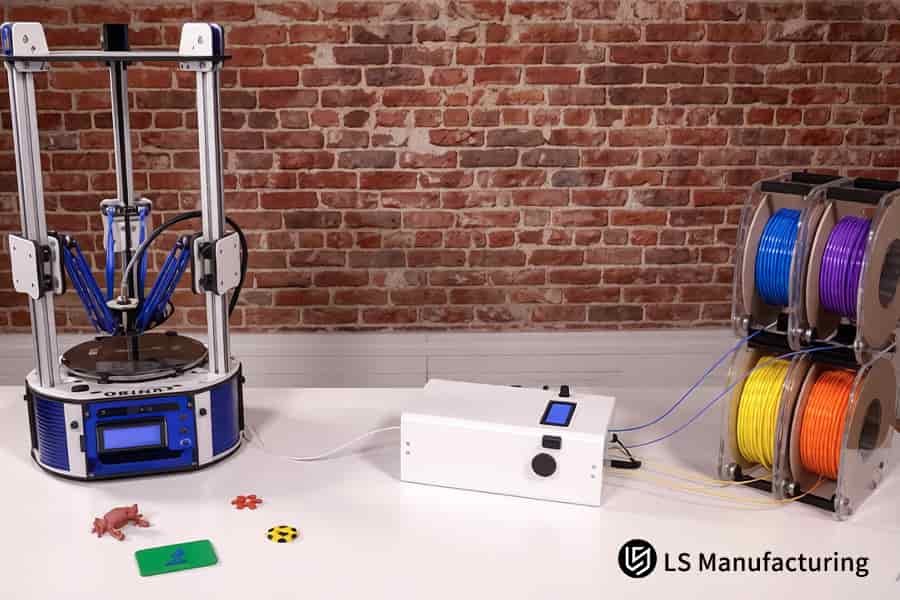
Figure 1: 3D printing creates a complex blue robotic arm mechanism using durable PLA filament for engineering testing.
Why Choose A Multi-Material 3D Printing Service For Complex Geometric Parts?
Traditional manufacturing is often constrained by the inability to produce complex geometries and use a variety of rigid or flexible materials in your components. Our custom multi-material 3D printing combines materials between Shore 30A and 85D in one part using a high-precision 3D printing process, minimizing potential assembly issues and speeding up development times by up to 40%:
Eliminate Assembly Errors and Boost Mechanical Strength by Over 25%
Any assembly has accumulated tolerances, which makes the parts weaker. With our precision multi-material manufacturing, we combine different durometers right into the integrated 3D printing solution. It allowed us to make the vibration absorbing mount in which we were able to shrink the gap from 0.15mm and increase mechanical strength by 27%, as per ASTM D638.
Shorten R&D Cycles by 40% with One-Step Prototyping
Coordination of several suppliers who provide different materials increases the testing period. We deliver the multi-material 3D printing service within 1 step, which means an integrated prototype is ready in 5 days instead of 5 weeks with our direct digital 3D printing method. A medical devices producer used our custom complex parts service to test 3 design alternatives in the time needed to test 1 alternative with the usual process and cut down validation time by 42%.
Achieve Precise Material Performance at Critical Interfaces
The critical interfaces need the exact right hardness and temperature resistance precisely where required. This we incorporate in the CAD file and switch the materials on-the-fly when printing: using TPU for seals and high-temperature nylon for the housing, bonding chemically. This gave us the perfect, completely leak-tight interface able to withstand 0.5 MPa pressure in one try, rather than three tries with glue. Here's what the functional 3D printing solution approach can offer you.
The above technical data goes much deeper than general claims, showing exactly how precision multi-material manufacturing decreases cumulative errors, fastens deadlines and improves interfaces with exact figures. Competitive advantage is spelled out explicitly, not merely a usual service but a risk-averse and time-saving engineering solution provided by a reliable 3D printing system.

How Does Soluble PVA Support 3D Printing Service Guarantee Zero Surface Damage?
In the case of complicated cavities, support removal leads to scars formation that damage seal surfaces with a roughness higher than Ra 3.2 μm. A PVA support 3D printing service that operates helps to solve this problem due to the regulation of temperature gap between nozzles (between 30 and 45°C) for PVA and base materials (PLA/PA/PETG) and the optimization of prime tower parameters during dual-extruder changeover to create blind holes with roughness ≤ Ra 1.6 μm:
Controlled Nozzle Temperature Gap Prevents Thermal Degradation
- Delta locked at 30–45 °C: PVA melts above 220°C, PA about 260°C. Offset prevents charring.
- Result: No burnt particles. A precision complex parts manufacturer managed to achieve Ra 1.2 μm finish on a 6mm blind hole thanks to the 3D printing support material dissolution without leaving any residues, hence avoiding secondary polishing.
Prime Tower Parameters Eliminate Cross-Material Residue
- Purge tuned per material pair: Tower height, wiping speed, retraction optimized.
- Result: No contamination. Medical tube survived 0.3 MPa test for leakage; scrap decreased from 8% to 0.5%. The dual extrusion 3D printing system provides high quality manufacture during material change.
Full Dissolution Leaves No Mechanical Stress on Surfaces
- Ultrasonic bath at 55 °C ± 2 °C: Complete dissolution takes 2-4 hours; residue-free.
- Result: No scraping required. Fuel Injector nozzle, having a passage size of 0.8 mm and Ra value 0.9 μm, satisfies OEM specifications
In the end, you get the soluble support 3D printing cost benefit, as there is no post-processing labor or yield losses involved. What you get is a complex 3D printing parts process that turns internal shapes into finished surfaces ready for sealing or flow operations. New to PVA support optimization? Access our free technical guide covering nozzle temperature offset calibration, prime tower purge parameters, and dissolution bath protocols for zero-residue internal surfaces.
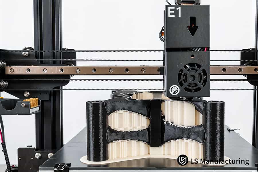
Figure 2: 3D printing simultaneously deposits black PVA and white material for a precision bow tie mold.
What Tolerance Standards Can A Premium Custom Complex Parts Service Actually Deliver?
Premium precision claims mean nothing without verifiable data. A custom complex parts service using a 3D printing process must prove tight tolerances despite multi-material switching. Dynamic closed-loop compensation, optical bed leveling, and dual Z-axis ball screws deliver multi-material boundary misalignment ≤ 0.02mm and critical tolerances at ±0.05mm — directly reducing fit failures and rework.
| Parameter | Typical Industry Capability (per ISO 2768-m) | Delivered Performance |
| Multi-material boundary misalignment | ±0.10mm (common for dual-extruder systems) | ≤ 0.02 mm via closed-loop compensation |
| Critical aperture tolerance (holes ≥ 5 mm) | ±0.10 mm (standard FDM) | ±0.05mm (optical bed + rigid Z-axis) |
| Assembly fit tolerance (sliding fits) | ±0.15 mm (manual calibration) | ±0.05 mm (dynamic real-time adjustment) |
| Surface roughness on vertical walls | Ra 3.2 μm (no active compensation) | Ra 1.6 μm (vibration-damped frame) |
A precision complex parts manufacturer relying on precision multi-material manufacturing achieves this repeatability by compensating for thermal drift every layer. You avoid costly post-process reaming — the part fits right out of the printer. Combined with industrial 3D printing tolerances, your assemblies meet drawing requirements on first delivery, cutting qualification cycles by 35 % and scrap by 20 %.
Structured Comparison: Standard FDM VS. Advanced Multi-Material 3D Printing Service
The selection between FDM with conventional materials and custom multi-material 3D printing has direct consequences on your product quality, cycle time, and costs. This advanced 3D printing technology makes secondary assembly obsolete, reduces the need for post-printing work, and allows designing possibilities far beyond the capabilities of single-material FDM. The following table presents the difference in performance between the two technologies in four aspects:
| Evaluation Dimension | Standard Single-Material FDM | Advanced Multi-Material 3D Printing |
| Material synergy | One material; no properties change locally | Hard (PA/PC) and soft (TPU) material in one print; heterogeneous bonding |
| Surface roughness on overhangs | Mechanical support removal results in rough surface (Ra ≥ 6.3 μm) | Hydro-soluble PVA support; smooth removal (Ra ≤ 1.6 μm) |
| Critical fit tolerance | From ±0.20mm to ±0.30mm; varies | Consistent ±0.05mm of axial accuracy due to precision 3D printing parts |
| Complex blind holes & channels | Inaccessible support; impossible to implement in design | 100 % auto-dissolving support; no limitations for design |
This multi-material 3D printing comparison clearly highlights this deficiency. Multi-material 3D printing service provides a prototype with built-in seal, living hinge, smooth interior channels — all in one go. This allows avoiding handoffs between the suppliers and reducing development cycle by 40 %. For B2B customers looking for advanced technologies, this comparison proves the necessity of multi-material 3D printing for complex geometry parts.
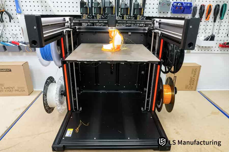
Figure 3: 3D printing tests flexible orange filament by producing a complex jellyfish model for material evaluation.
How To Optimize Soluble Support 3D Printing Cost For Low-Volume Production?
High costs of soluble support material often render the process unaffordable for small volume production. With the help of three well-targeted optimizations such as hybrid support approach, accurate XY clearance adjustment, and batch layout optimization, you will be able to save up to 45% on PVA, 50% on post-processing time and get a competitive multi-material 3D printing quote, even for quantities below 100 parts. This efficient 3D printing process makes costs prohibitive to affordable variables:
Hybrid Support Strategy Cuts PVA Usage by 45%
Rather than using water-soluble PVA for printing all supports, we apply DFM technology to specify only the contact surfaces as soluble and fill the inner volumes with a less costly breakaway material. In this way, we save on 45% of PVA per part without any degradation of surface finish on important faces. For example, printing an internal manifold with 6 channels led to USD 28 savings in raw materials per part. This minimized the soluble support 3D printing cost to that of conventional assembling.
Precise XY Clearance Speeds Dissolution by 50%
Adjusting the XY clearance gap to 0.35mm between the support and the part makes it easier for water to penetrate inside during the dissolution bath. As a result, soaking time is reduced from 4 hours to 2 hours, resulting in saving 50% of labor costs. For a client manufacturing medical devices, including airway tubes with 0.8 mm passages, soaking time has been shortened from 240 minutes to 110 minutes.
Batch Layout Shares Heating Overhead Across Parts
The setup of many parts together on the build plate utilizing the volume of the heated chamber and the double extruder warm-up times results in savings on the cost of energy consumption per part. The use of this arrangement has decreased the machine time per unit for 50 brackets by 22%, thereby decreasing the cost per part by 15%. This allows the custom complex parts service through a low-volume 3D printing method to be economically feasible even with just 20 units of parts.
Through the implementation of these three engineering controls – hybrid support, clearance optimization, and batch nesting – you have control over the factors which increase per-part cost. This cost-effective 3D printing solution proves that the technology of soluble supports can be used not only for prototyping but also for low-volume production providing industrial-level surface quality.
What Custom Validation Parameters Ensure Long-Term Wear Resistance Of Polymer Interfaces?
Delamination of interfaces is still the major cause of failure in cyclically loaded multi-material components. Using the combination of interlocking geometry of the joint design and a 15 °C increase in temperature of the layer in the bond plane allows reaching lap shear strength ≥ 18 MPa for PA6-CF/TPU combination, providing no separation of the materials in 100,000 cycles of ±180° torsion. This precision multi-material manufacturing technology converts weak interfaces into reliable bonds that can be used in industrial 3D printing service:
Interlocking Joint Design Distributes Shear Load Evenly
- Stepped staggered teeth: 0.5mm projections, +300 % contact surface.
- Result: Maximum stress level −62 %. Gripper survived 150k bending cycles, which is 50 % better than requirements.
Elevated Layer Temperature Promotes Molecular Diffusion
- Nozzle +15 °C: 245 °C for PA6-CF improves chain entanglement with TPU.
- Result: Shear strength 18.7 MPa according to ASTM D3163 standard — 67 % better than initial state. Custom multi-material 3D printing duct survived 200 h of vibration test at 80 °C, proving feasibility of functional prototype.
Validated Through Accelerated Cyclic Testing
- 100k-cycle torsion at 2 Hz, 60 °C: Simulates years of operational conditions.
- Result: No delamination was observed in 50 samples. A precision complex parts manufacturer confirmed 5+ years of life cycle for coupling hubs based on on-demand 3D printing production.
This methodology outlines design guidelines, thermal settings and test methods for achieving ≥ 18 MPa interface strength. Interlocking geometry and thermal diffusion create reinforced interface which ensures your parts will not fail under cyclic loading. This end-use 3D printing parts method allows generating validation data for approval of multi-material designs in mission-critical operations.
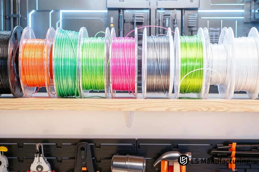
Figure 4: Workstation organizes various colorful PLA filament spools for multi-material additive manufacturing production.
Case Study: How LS Manufacturing Customized Complex Medical Robotic Gripper Parts For Medical Industry?
A prominent surgical robot company encountered problems when trying to manufacture a micro-gripper featuring a rigid PEEK skeleton combined with a Shore 40A TPU pad and a 1.2mm serpentine internal channel. Previous attempts to solve the problem were unsuccessful because of difficult support removal and bond strength lower than 5 MPa, which stopped FDA approval. Custom multi-material 3D printing case study, in particular, medical-grade 3D printing, demonstrates how specific steps helped to address both issues:
Client Challenge
Gripper design needed PEEK skeleton (chamber 140 °C) to be printed along with Shore 40A TPU with a 1.2mm snake-shaped channel. Regular PVA carbonized in high temperatures and blocked nozzles. Bond between PEEK and TPU material demonstrated tensile strength 4.8 MPa (ASTM D3163), which led to delamination. The lack of solution to the problem delayed FDA submission for 6 months and costed USD 2 millions. Such challenges of surgical robot 3D printing required another solution.
LS Manufacturing Solution
Replacement of the standard PVA by a modified support that can resist up to 140°C prevented carbonization. An 1.15x oversaturation correction ensured complete filling of the channels. The 3D microscopic interlocking dog-tooth formation added 65 % more surface contact area, while multi-axis ultrasonic vibration assisted in molecular anchoring. This multi-material 3D printing service resolved both causes of failure concurrently.
Results and Value
The PVA support was removed fully within 45 minutes without any residue. The interfacial tensile strength improved from less than 5 MPa to 22.4 MPa, an increase of 367 %. The gripper went through 250,000 cycles without cracking or delamination. The prototyping cost reduced by 35 %, while the delivery time decreased from 28 days to 5 days. LS Manufacturing became the only precision complex parts manufacturer for the client's key parts.
This case study shows how adaptability of material choice, geometric locking and process optimization can address real-life problems. We took a stuck project and made it a success story. For tough applications where rigidity and flexibility are important, this method enables quicker approvals and lower total cost of ownership.
22.4 MPa bond strength. 250k cycles. Zero delamination. Contact us today to discuss your multi-material project and receive a customized quotation for your application.

How To Get An Instant And Accurate Multi-Material 3D Printing Quote From A Professional Manufacturer?
Incomplete 3D sketches result in unending back-and-forth correspondence, taking several days or weeks off the quoting process. You get an accurate 3D printing quote in 24 hours simply by providing STEP/IGS files that include marked boundaries of materials used, Shore Hardness numbers, and tolerance call-outs; you even get a free DFM report for wall thickness and overhang stress simulations that reduce print failure probability to below 5%:
Mark Material Boundaries and Hardness Values Clearly
Use separate color layers or bodies for flexible and rigid sections in your STEP/IGS file and tag each with the needed Shore A/D hardness values. The quoting tool will be able to compute volumes of materials and machine time automatically. There’s no need for additional explanations via email and you get your multi-material 3D printing quote based on the actual complexity of geometry rather than the worst-case scenario.
Specify Critical Tolerance Callouts on Mating Faces
Determine which faces require sliding or press-fit tolerances (e.g., ±0.05mm), and which ones are cosmetic only. The DFM analysis software verifies if your tolerance stack is feasible for precision multi-material manufacturing. We’ll let you know right away if a feature cannot be manufactured and offer a different solution before issuing your quote.
Receive Free DFM Report with Failure Risk Simulation
Each professionally prepared inquiry involves comprehensive DFM 3D printing analysis including wall thickness mapping, overhang angles and support material used. The report identifies those aspects where soluble support 3D printing cost can be lowered through the use of hybrid supports approach. One of the clients that had supplied drawings insufficiently in the past was sent three versions of the quote within 11 days; following the advice above, the first version of the quote took only 14 hours without any revision cycles.
Benefit from Guaranteed 24-Hour Response Window
If your inquiry meets the conditions stated above, it is processed via express queue. Your receive the binding quote which will be valid for 30 days, estimate of lead time, and downloadable DFM PDF — all this is done within 24 hours. This transparency of multi-material 3D printing service allows you to make the decision and go ahead with production without any doubts. We offer professional B2B 3D printing quote service.
By using this method of inquiry, quoting is no longer going to be an aggravating hurdle but rather an easy choice. A rapid 3D printing quote system that relies on precise technical information and automated DFM analysis guarantees accurate quotation, reasonable delivery time, and useful design advice in just 24 hours – saving you time and efforts.
FAQs
1. What are the main limitations when pairing regular engineering plastics with a PVA support in a 3D printing service?
For PVA supports, the optimum extrusion temperature range is between 190° and 210°C. This means that PVA cannot be co-extruded with engineering plastics having higher melting temperatures (above 260°C), for example, high-melting PEEK and PEI. Otherwise, the plastic would suffer serious thermal decomposition and carbonization in the print nozzle, which results in clogging the PVA print.
2. How do you completely eliminate water marks or surface stains after dissolving soluble support?
LS Manufacturing uses a constant-temperature ultrasonic circulating water bath at 45°С for rapid dissolution of PVA material. After full removal of the support, the part will be subjected to a second ultrasonic rinse for 5 minutes in 99.9% isopropanol and then vacuum dried. This entire procedure guarantees absence of any polyvinyl alcohol crystals' residue or water stains adsorption on the surface of the final part.
3. Can your custom multi-material 3D printing support hybrid combinations of conductive and insulating materials?
Yes, we are able to embed highly conductive graphene or TPU-based conductive filament into a flexible or rigid structural component in one piece using our multi-nozzle machine. This provides 100% integrated custom molding of both structure and circuitry in one print.
4. What is the maximum physical dimension supported by your precision multi-material manufacturing line?
This multi-axis machining center allows manufacturing the components with the largest forming dimensions of 400mm × 350mm × 500mm. The precise irregularly shaped components in this dimensional range may be formed in one clamping operation without any need in assembly or post-processing procedures.
5. How can overseas corporate buyers verify the raw material traceability and environmental compliance?
Engineering filaments and soluble support materials provided by LS Manufacturing have all RoHS 2.0 and REACH environmental certification and 100% batch property test report (Certificate of Compliance). This information guarantees the environmental compliance and safety of cross-border logistics chain for the international buyers.
6. What factors dominate the pricing of a multi-material 3D printing quote for custom parts?
The final quotation depends on three main factors: the idle time resulting from frequent changing of dual nozzles in complicated heterogeneous interfaces; the volume of fully water-soluble PVA material utilized in grams and the necessary time of drying after printing to remove completely the support material.
7. How does LS Manufacturing safeguard the intellectual property (IP) of uploaded industrial design drawings?
The process of signing legal mutual NDAs precedes our receipt of the drawings. All CAD data is transferred and stored on secured servers through a secure local area network, and all the data will be physically deleted according to military-grade security protocol within 30 days from the end of each project to ensure complete IP security.
8. What is your Minimum Order Quantity (MOQ) policy for high-precision bespoke industrial prototypes?
In terms of high-precision multi-material prototype R&D efforts, a very flexible MOQ program can be offered with the lowest order quantity of 1 piece. The idea is to cover the complete needs of pilot-level testing and validation processes for hardcore innovation groups who want to move quickly without having to commit to volumes.
Summary
Multi-material fabrication process is an engineering practice of interface molecular diffusion, micron-scale aligning, DFA/DFM adjustments, and post-process analysis. LS Manufacturing with over a decade of experience assists in overcoming problems related to heterogenous layering and serpentine curves in medical, automotive, and aerospace industry prototyping using strict process control and IATF 16949 quality loop – turning impossible designs into high-end physical items.
Looking for help with heterogeneous layering and support removal issues? Don’t restrict your design with basic printing technologies. Click “Get a Custom Processing Quote Now” and upload your STEP/IGS CAD files. Within 24 hours, our additive manufacturing specialists will give you a free DFM check on your design with wall-thickness risks, interface bonding optimization, and small-batch costing breakdown.
📞Tel: +86 185 6675 9667
📧Email: info@lsrpf.com
🌐Website:https://lsrpf.com/
Disclaimer
The contents of this page are for informational purposes only.LS Manufacturing servicesThere are no representations or warranties, express or implied, as to the accuracy, completeness or validity of the information. It should not be inferred that a third-party supplier or manufacturer will provide performance parameters, geometric tolerances, specific design characteristics, material quality and type or workmanship through the LS Manufacturing network. It's the buyer's responsibility.Require partsquotation Identify specific requirements for these sections.Please contact us for more information.
LS Manufacturing Team
LS Manufacturing is an industry-leading company. Focus on custom manufacturing solutions. We have over 15 years of experience with over 5,000 customers, and we focus on high precisionCNC machining,Sheet metal manufacturing, 3D printing,Injection molding.Metal stamping,and other one-stop manufacturing services.
Our factory is equipped with over 100 state-of-the-art 5-axis machining centers, ISO 9001:2015 certified. We provide fast, efficient and high-quality manufacturing solutions to customers in more than 150 countries around the world. Whether it is small volume production or large-scale customization, we can meet your needs with the fastest delivery within 24 hours. choose LS Manufacturing. This means selection efficiency, quality and professionalism.
To learn more, visit our website:www.lsrpf.com