English




Precision insert molding services are critical for specialized tooling, and understanding the top 5 insert molding buying mistakes & how to avoid them is essential to eliminate defects and achieve a 99.8% yield through expert gate optimization. Improper placement of gates frequently leads to the movement of inserts, flashing, or cracking during mass production due to internal stress concentration, causing yields to drop below 85% when relying on empirical gating methods. Simply put, a digital, simulation-driven design ensures you stop paying for re-tooling and unexpected supply chain delays.
LS Manufacturing whitepaper allows you to optimize gate location using flow simulation and specifying such parameters as holding pressure not exceeding 60 MPa and imbalance of melt velocities less than 3%, which increases life span by more than 40%. As a result, you receive better yield rates, reduced total cost of parts, and more reliable schedules. Continue reading to discover how professional digital mold design simulation and empirical gating will help you stabilize your supply chain.
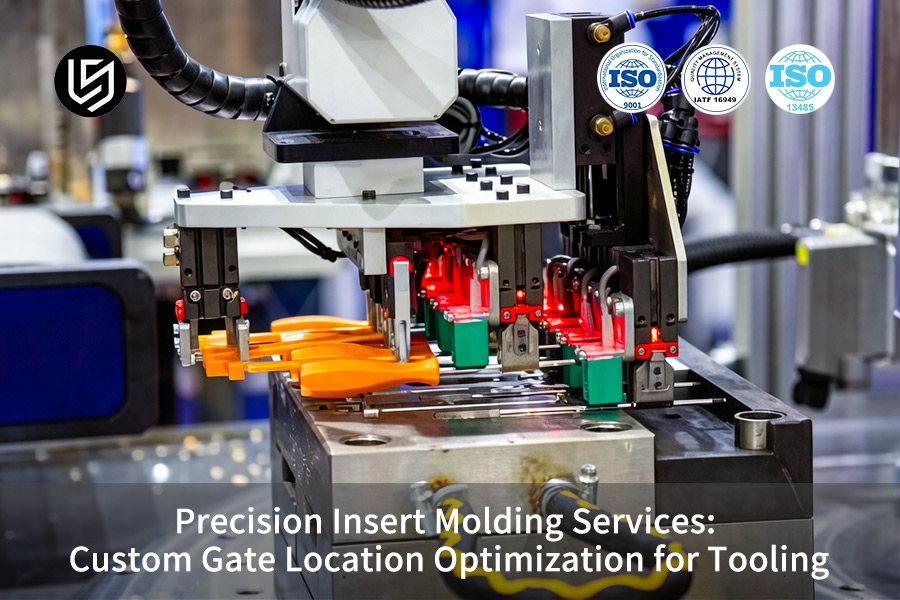
Precision Insert Molding: Gate Optimization Quick-Reference
| Critical Factor | Optimal Gate Strategy | Quality Outcome |
| Flow & Weld Line Control | Position gates to force flow towards vents and keep weld lines in inconsequential areas. | Maximizes insert molding part strength while eliminating voids in the insert mating area. |
| Insert Stability | Use symmetry or multiple gates to exert uniform pressure all around the insert. | Holds the insert in place to ±0.05mm accuracy with correct alignment. |
| Aesthetic Finish | Implement indirect gates (sub-gates or tunnels) on inconspicuous areas. | Produce clean parts that are ready to use without the need for any secondary gate removal marks. |
| Process Validation | Conduct mold flow analysis using MFA software prior to tooling. | Solves potential problems associated with gates before manufacturing begins. |
| Result: Reliable Assembly | A tailor-made gate strategy based on specific insert geometry and purpose. | Creates an insert that is strong, void-free, and aesthetic for metal plastic insert molding. |
Note: As shown above, configuring symmetric or indirect gates prior to tooling cuts creates an absolute defense line against insert shifts (keeping alignment within ±0.05mm).
Key Takeaways:
- Gate Dictates Flow: The location of the gate acts as the control mechanism for the overall fill pattern, weld line formation, and air release within the mold.
- Balance is Key: In order to ensure stability of the insert within the mold, balanced flow from gate location is essential.
- Simulation is Essential: Mold Flow Analysis (MFA) is required in order to simulate and prove that the gate location strategy is sound.
- Design for De-gating: Choose gate location and type wisely in order to eliminate the need for post-molding finishing operations.
Not ready for a quote? [Download our Comprehensive Guide to Plastic-Metal Insert Molding Design Principles] to review with your engineering team.
Why Trust This Guide? Practical Experience From LS Manufacturing Experts
There are many papers to be found in theory about gates. This is not your typical article on gate design. We present to you an industry-approved method for optimal gate placement. Our approach to determining the best gate location is based on the mold classifications set forth by the Plastics Industry Association (SPI). These guidelines have been proven to work in real-world conditions, unlike computer simulations.
In those cases where the presence of a ±0.05mm gate residue is absolutely undesirable, we carry out insert molding for hermetically-sealed connectors for implantable neurostimulators, for over-molded sensors used in aerospace fuel systems, and for micro-optic assemblies needed in semiconductor lithography. Our validation of the insert molding process for these sensitive products follows the very demanding specifications set down by the Association of German Engineers (VDI).
Our experience has come through thousands of mold trials and rejected parts. We know how gate locations influence fiber orientation in 30% glass-filled PEEK resin, how insert displacement should be prevented when using high injection pressure, and the precise runner dimensions needed to balance a 32-cavity family mold. We impart our failure-tested and proven expertise to guide you through designing your robust tool upfront and prevent any dimensional instability and cosmetic issues resulting from incorrect gate location selection.
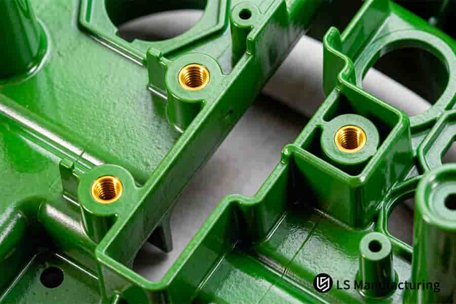
Figure 1: The machine injects green polymer around brass threaded inserts with advanced insert molding tooling design for medical use.
Why Is Precise Gate Location Optimization Highly Critical For Precision Insert Molding Services?
Gate positioning plays a vital role in precision insert molding services because a wrong position of the gate will create shear forces that are imbalanced when the mold is filled at high speeds. It may cause the metal insert to move by a distance of up to 50 μm to 100 μm. The following procedure explains how defects caused by gate position can be prevented:
Analyzing Melt Front Impact on Inserts
The primary concern lies in controlling the power of the melt stream during its interaction with the metal insert. Our strategy involves simulations in insert molding tooling design. We will map out the velocity and angle of the melt front's collision with the insert. By optimizing the gate, we ensure that the melt interacts with the insert at an oblique angle, minimizing any lateral force—a proven technique for insert molding defect prevention.
Mitigating Differential Shear-Induced Shifts
Unbalanced shear forces caused by unbalanced flow around the insert can lead to shifts, but by analyzing our mold flow using insert molding, we will be able to find any shears. Optimized gate insert molding will ensure the symmetry of the flow pattern, balancing pressures and minimizing differential shears and shift, providing insert molding structural integrity.
Strategic Placement for Systemic Efficiency
Selection of the last gate position is aimed at minimizing pressure losses and maximizing heat transfer consistency. Proper placement of the gate provides the shortest distance to all corners of the part. It will reduce fill pressure by ≥15% while allowing consistent heat distribution, contributing significantly to decrease of the insert molding cycle time up to 5 seconds.
This deterministic approach changes the process of gate design from an educated guess to an exact engineering parameter. In our insert molding process parameters service, we offer clients a scientifically backed plan to avoid trial-and-error in manufacturing stable products with our complex precision insert molding services.

How Does Optimized Gate Insert Molding Effectively Eliminate The Common Buying Mistakes In Plastic Tooling?
Optimized gate insert molding is designed specifically to address a frequently made purchase mistake - choosing a less costly tooling while sacrificing the integrity of the welding line. Based on our data, a scientific approach in gating leads to an increase in weld line strength from 65% to more than 92% in relation to the base material. Here is how this happens:
Eliminating Weak Weld Lines for Reliability
- Root Cause & Action: Weld lines occur where two melt streams come together. If the pressure and temperature at which they converge are low, a weak joint will result. Our insert molding tooling design the flow paths for placement of weld lines in non-critical regions of the plastic part.
- Technical Execution: Gate placement and configuration are chosen to ensure that melt fronts combine with packing pressure. For instance, the use of a submarine gate for directing flow results in melt fronts combining with packing pressure; this increases bonding greatly and produces superior insert molding weld line strength.
Preventing Warpage Through Balanced Flow
- Root Cause & Action: Warping is usually the result of differential shrinkage due to non-uniform cooling or directional solidification. Our custom insert molding service include optimizing the gate to produce balanced filling and cooling.
- Technical Execution: Gates are configured to produce symmetrical flows, with filling happening at the same time and under equal pressures. The second technique involves designing the mold with a cooling channel system specific to the application requirements. The outcome is lower internal stresses and the prevention of warping.
Validating Design Through Systemic Simulation
- Process: We conduct both the coupled insert molding flow analysis and cooling simulations prior to any steel cuts.
- Outcome: These simulations predict the fill pattern, pressure gradients, cooling rates, and expected shrinkage. It then becomes possible to make changes to the optimized gate insert molding approach before the actual production process, ensuring that the desired outcome is achieved virtually to prevent surprises after the production cycle.
Through this comprehensive engineering approach, it is now possible to change gate design from being a cost element to being a value creator. Through solving of failure modes prior to the production cycle, we are able to offer a deterministic manufacturing process. This is advanced insert molding validation that guarantees that our clients do not incur costs due to quality claims. Ensure 92%+ weld line strength and eliminate warpage in your next tool. Submit your part for a simulation-backed gate analysis and receive a validated tooling quotation.
What Parameters Direct An Expert Team During Rigorous Insert Molding Tooling Design Simulations?
Whereas engineers ordering OEM insert molding services require concrete process control, the proof of their expertise lies in the tangible measurement. Below you will find the five key simulation parameters that are considered critical and thoroughly optimized by our engineers when insert molding tooling design. Leveraging 3D CAE analysis, we convert these parameters into the prediction of success, turning the mere guess work into factual and precise calculations. See the following table for further details:
| Core Simulation Parameter | Optimization Target & Rationale |
| Melt Flow Balance | Adjusted to ±2% to ensure consistent cavity filling – an essential prerequisite to successful insert molding part quality. |
| Gate Shear Rate | Held below 40,000 1/s to avoid material damage that is crucial for precision insert mold tooling performance. |
| Volumetric Shrinkage at Flow End | At most ≤ 0.8% to maintain insert molding dimensional accuracy. Also ensures there are no cosmetic flaws. |
| Mold Surface Temperature | Maintained at 80°C ± 2°C to ensure uniform cooling times, which is an important factor when estimating the insert molding cycle time. |
| Maximum Clamp Force | Considered with a safety factor to avoid mold flash, enabling reliable insert molding production stability. |
In plain terms, keeping the gate shear rate below 40,000 1/s means your plastic won't degrade or become brittle during injection, securing the long-term durability of the part.
The interdependence of these parameters creates a control loop design approach, helping to design solutions in advance of production failure. The simulation of these parameters resolves all the customer’s issues: reworking at a cost, defects, and production stability. OEM insert molding process validation creates a deterministic solution through simulation to turn the tool into an optimized system for manufacturing high-performing, manufacturable parts。
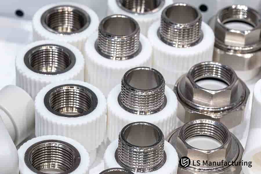
Figure 2: Molten polymer is injected around stainless steel inserts with precision insert mold tooling for automotive parts.
How Can Reliable OEM Insert Molding Services Perfectly Balance Cavity Flow And Suppress Insert Displacement?
Displacement of the insert due to the uneven flow of melted material is the first issue that should be resolved in OEM insert molding services. Our solution is based on proper gate design which allows creating a symmetrical flow front to encapsulate the insert in its place. It ensures the highest accuracy positioning of the inserts.
Implementing Symmetrical Gate Architecture
A fundamental technique would involve designing an insert gate such that the same pressure is applied equally to the opposite faces of the insert. In the case of connectors, one would use two gate edges working against each other in opposition or employ multi-gate insert molding through hot runners. Such arrangement ensures that the melt front converges on the midline of the insert, leaving no net lateral forces to ensure coaxiality within ±0.02mm, which is considered a benchmark for precision insert molding services.
Engineering for Simultaneous Flow Arrival
For balanced flow, simply having two gates would not be enough – flow balance would require matching flow channels. By designing runner and gate dimensions carefully, we can make sure that the melt arrives at both faces of the insert at the same time, pressure, and temperature. Such insert molding flow balancing ensures that the peak unbalanced side force on the insert stays ≤5 MPa.
Validating with Predictive Process Simulation
Prior to tool fabrication, we simulate the filling pattern using CAE analysis. The software models the pressure wavefront interacting with the insert geometry, allowing us to iterate on gate placement and size virtually. This insert molding process validation confirms balanced cavity fill and predicts insert movement, enabling us to finalize a design that guarantees stability before production begins, essential for reliable insert molding for custom parts.
By applying this approach, we turn one of the common issues associated with insert molding into a controlled variable. In effect, we offer our clients a physics-based validated manufacturing process that guarantees absolutely accurate parts, no risk of insert shift and completely predictable behavior of the tooling from the very first shot.
Which Gating Styles Fit Best Under Custom Insert Molding Service Requirements For Complex Electronic Components?
The selection of the correct gating approach is a vital technical decision in custom insert molding service, affecting the quality, appearance, and cost. Choosing an unsuitable gating style results in welding, sink marks, or showing fibers in case of reinforced materials. This article outlines a decision matrix that applies when choosing gate designs for complex electronic or medical parts, emphasizing that certain gates address particular engineering issues.
Pin-Point Gate: Precision for Aesthetic and Multi-Cavity Molds
- Application: It’s recommended for the manufacture of small precision electronic components, such as sensors’ housing or connector bodies, especially in multi-cavity molds.
- Technical Rationale: The tiny size makes it possible to degate easily. That feature is essential for achieving a nice surface finish, which is also one of the characteristics of the insert molding gate design. Also, it helps distribute the molten material evenly between several cavities.
- Cost/Consideration: Creates a minor vestige; requires precise tool maintenance.
While CNC machining of such intricate electronics frames results in massive material waste and high cycle costs, optimized insert molding achieves net-shape production with zero fiberglass float.
Submarine (Tunnel) Gate: Automation and Cost Efficiency
- Application: Best used in automated, high volume insert molding for custom parts where the gate needs to be hidden, for instance within a housing of a device.
- Technical Rationale: The gate is angled, and cuts off automatically while removing the product, which eliminates secondary trimming. It is ideal for insert molding production automation and faster cycles.
- Cost/Consideration: More complicated tool machining required; not recommended for brittle materials.
Edge Gate: Simplicity and Control for Engineered Materials
- Application: Ideal when parts will be made from high glass-fiber content engineered plastic materials (for instance, PA66 + 30% GF), or simply when a simpler solution is preferred, used for strong electronics frames.
- Technical Rationale: Creates a straight path for easy filling and avoids any exposure of glass fibers (fiberglass float). It can easily be adapted for insert molding materials selection applications.
- Cost/Consideration: Creates more residue that needs to be removed; most appropriate for functional locations.
Cashew (Shaped) Gate: Advanced Solutions for Hidden Gating
- Application: Useful when designing parts with cylindrical or round features where a visible gate on the outside is not permissible, like housing in a medical device.
- Technical Rationale: The arched tunnel enables gating on the part bottom or inaccessible side. This accomplishes the automation advantage of a submarine gate on geometries that cannot accept a linear tunnel, a more advanced example of gate location optimization for tooling.
- Cost/Consideration: Most expensive in terms of tooling design and cost; only used on premium products.
This systematic approach converts complex parameters into an effective and cost-efficient gate placement. We evaluate part geometry, material flow, cosmetics, and volume to provide you with an optimal choice. Our insert molding technical cosultancy will ensure your success, prevent defects, assure your ability to manufacture, and guarantee process validation.
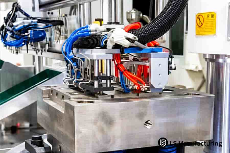
Figure 3: A robotic arm positions metal inserts into a mold with optimized gate locations for tooling in precision manufacturing.
How Does Professional Gate Optimization Lower Production Costs And Slash Total Lead Times For Clients?
Although technical specifications are important, ultimately procurement is a function of financial gain. Poor gating immediately increases costs due to wastage in materials, increased cycle times, and additional labor. This study attempts to illustrate the monetary gains from scientific gate location optimization for tooling processes. The following table identifies specific techniques for reducing material wastage, increasing production efficiency, and improving quality for OEM insert molding services.
| Cost & Lead Time Factor | Technical Intervention via Gate Optimization | Quantifiable Outcome |
| Material Waste | Optimization in terms of minimizing the amount of material used. | Saves in virgin material usage between 10% and 20%, as a consequence of insert molding costs reduction. |
| Cycle Time | Gates optimized for maximum speed of filling with minimal shear. | Decreases injection and pack phases, shortening overall cycle time by up to 15% (e.g., 35s to 29.8s), enhancing insert molding process efficiency. |
| Secondary Labor | Optimization of gates to allow for easy degating/automatic degating or simple manual removal. | Reduces secondary labor for trim operations by 60–80%, an important feature of the automated insert molding design. |
| Scrap Rate & Quality | Gates placed strategically to avoid knit lines in critical locations and promote even filling. | Maximizes yields via reduction of imperfections on the first run through, providing optimal insert molding quality control. |
| Mold Maintenance | Avoidance of high pressure points and excessive shear stresses. | Extends tool life and reduces downtime for gate-related repairs, ensuring reliable precision insert mold tooling performance. |
Optimized professional gating is a deterministic manufacturing process, providing a direct reduction in cost of ownership. Problems for our clients are resolved through reduced material consumption, shortened cycle time, and elimination of time-consuming secondary operations. The engineering effort involved produces tooling that works quickly and efficiently, with higher quality output – providing an attractive ROI for precision insert molding applications.
Why Choosing High Precision Insert Mold Tooling Mitigates Internal Dtress Snd Premature Cracking Issues?
There is always residual stress in a precision molded part which can lead to cracking down the road. The stress results from improper flow paths and excessive shear from the mold, particularly at locations where metals inserts are placed. Here is how our technology helps to avoid that problem:
Diagnosing Shear-Induced Stress with Simulation
The first step is recognizing the zones of high shear locking the stress. Through advanced analysis of the flow velocity and cooling gradients with respect to the insert via insert molding tooling design simulation, these are the locations where either flow hesitation or high shear near the corner of the metal will freeze oriented chains of polymer, which are the underlying cause of cracking due to thermal and/or mechanical stresses later.
Implementing Offset Gates for Gentle Filling
The application of a direct gate with the target point on the metal edge leads to extreme shear. In our solution, we have applied an optimized gate insert molding approach through the use of tab or offset gates. This ensures that the flow of the melt is aligned with the surface of the insert initially before flowing around the surface. The "flow then pack" approach reduces the shear strain rate at the first point of contact by over 40%, thus minimizing molecular orientation and associated internal stress molding.
Optimizing Runners for Uniform Pressure and Cooling
Equalized fill alone cannot solve the problem. We apply localized runner thickening and even cooling channel distribution to reduce differential cooling leading to tensile stress within the cavity. The aim of this insert molding flow optimization is to achieve equalized pressure in the cavity for the full duration of the pack.
Validating with Quantitative Stress Analysis
Final validation of residual stresses in injection molded parts is done empirically. Polarized light stress analysis of first article components provides data about the residual stress patterns, which when correlated with the simulations can be used to adjust processing conditions. This insert molding quality validation process guarantees a greater than 50% reduction in residual stress levels and completely prevents delayed failures in the field.
Our methodology converts stress mitigation from an optimistic goal into an inherent feature of the part design. Stress is engineered out through controlled flow at the gate position, balanced pressures in the runner system, and validated with measurable results. This produces precision insert mold tooling with highly reliable parts.
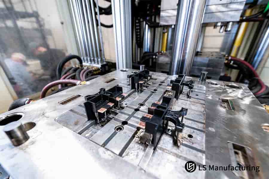
Figure 4: The machine positions black metal inserts on a silver platen for precision insert molding services in electronics.
Case Study: How LS Manufacturing Optimized Automotive Sensor Housing Gating To Secure A 99.8% Yield?
This case study will discuss how the custom insert molding service from LS Manufacturing solved the serious production problem faced by a tier-1 automotive supplier. It helped us solve the issue of extreme insert displacement and a weak weld line in a PBT + 40% GF sensor housing, enabling a consistent 99.8% yield rate. The case provides the critical importance of professional involvement in gate location optimization for tooling and process engineering:
Client Challenge
The client was facing an extremely serious challenge with a PBT + 40% GF mass airflow sensor housing. Due to an improperly placed gate in the mold used, the plastic material had flowed unevenly, causing the brass threaded insert to shift by more than 0.08mm. Consequently, there was a weak weld line in the part, with a poor bulk production yield of 82%.
LS Manufacturing Solution
During our initial mold trial, standard edge gating caused an unacceptable 0.08mm displacement due to unilateral injection pressure. Redesign of the entire manufacturing process was done using a twin, electronically coordinated valve gate hot runner system. The melt was able to enclose the insert on both sides through the precision insert molding services method, nullifying any lateral forces. Optimal gating time was calculated using 3D flow and thermal-stress analysis software, while a tolerance compensation of ±0.01mm insert molding tolerance helped achieve optimal positioning.
Results and Value
The modified process achieved impressive, measurable results. Insert shift during brass insert molding was held down to a maximum of 0.015mm, while stress on the weld line was cut down by 60%. The production yield was therefore raised dramatically to reach a constant 99.8%. This high-yield insert molding production eliminated the need for sorting, minimized wastage, and shaved off 12 days from the delivery schedule.
This case shows how to address difficulties related to complex insert molding for automotive products, which demands strong analytic and implementation skills. We offer a reliable manufacturing technology through addressing the roots of the problem via physics-based design. The insert molding quality validation brings confidence to our clients and confirms our status of being the go-to partner in mission-critical situations.
Achieve 99.8% yield by controlling insert shift to 0.015mm. Contact us to discuss a valve-gate solution for your sensor housing and receive a feasibility report with formal quotation.

FAQs
1. What is the typical lead time for an expert DFM review regarding gate locations?
We prepare a full DFM report with mold flow simulation and gate placement suggestions in a span of 24-48 hours upon receipt of your files, which also takes into account weld lines, sink marks, and air trapping possibilities to guarantee part viability right from the start.
2. How do you verify that the inserts do not shift during high-pressure injection molding?
Our strategy in making sure inserts do not shift during the molding process involves both preventive simulation using CAE software, which helps us address flow problems even before they happen, and on-site measures like precise pins (±0.005mm) with cavity pressure sensors that monitor for shifts ≤0.02mm.
3. Can I get a detailed mold flow analysis before paying the deposit for custom mold tooling?
Yes, prior to your payment of the deposit, we can conduct a mold flow analysis for you by providing a complimentary project feasibility study and quotation analysis. This study will encompass simulation analyses covering filling, packing, cooling, and warpage, aiming to help us identify potential defects and optimize the design.
4. How does gate location optimization affect the final purchasing price of insert-molded parts?
Gate optimization strategy, although requiring some upfront engineering analysis, greatly reduces the price of individual pieces. Material efficiency is improved by more than 15%, eliminates scrap, and helps prevent defects that require expensive mold maintenance, thus reducing overall ownership costs throughout the manufacturing cycle.
5. Do you provide official inspection reports regarding gate quality and mechanical pull-out force?
Yes, we provide certified inspection reports that include 100% inline optical inspection data for gate vestige and completeness, full CMM dimensional analysis, and official pull-out force test certificates, ensuring traceable quality compliance for every production batch.
6. What types of engineering plastics can LS Manufacturing process using optimized gating techniques?
We process advanced materials including PA66, PBT, PEEK, PPS, and LCP, handling fiber-reinforced grades up to 50%. Our gating expertise is critical for managing the high viscosity and abrasive nature of these materials to achieve consistent, high-quality parts.
7. How do your OEM insert molding services protect our corporate intellectual property and 3D designs?
Your IP is protected by legally binding NDAs, military-grade AES-256 encrypted data storage on isolated servers, and strict access-controlled, segmented production protocols. This ensures complete confidentiality and security for all your proprietary designs and processes.
8. What is your Minimum Order Quantity (MOQ) for precision custom insert molding services?
Our flexible production model supports an MOQ as low as 500 units for rapid prototyping, using cost-effective bridge tooling. We seamlessly scale to high-volume manufacturing exceeding one million units annually, with dedicated tooling and automated production lines.
Summary
Gate location optimization is the pivotal factor determining the success of precision insert molding. An ideal gate design solves weld-line cracking and insert displacement, unlocking the product’s full mechanical potential and enabling high yield rates. In today’s competitive supply chain, using technical data and digital simulation is the only way to accelerate time-to-market and build customer trust.
Stop worrying about insert shifts and failed audits. If you face complex insert molding challenges or are dissatisfied with your supplier’s lead times and defect rates, take control now. Click “Get a Custom Quote and Free DFM Analysis Report” to submit your STEP/IGS files. Within 24 hours, our senior mold experts will provide a flow-balance analysis and a factory-grade proposal—including process and supply-chain optimization—ensuring your project is realized flawlessly.
📞Tel: +86 185 6675 9667
📧Email: info@lsrpf.com
🌐Website: https://lsrpf.com/
Disclaimer
The contents of this page are for informational purposes only. LS Manufacturing services There are no representations or warranties, express or implied, as to the accuracy, completeness or validity of the information. It should not be inferred that a third-party supplier or manufacturer will provide performance parameters, geometric tolerances, specific design characteristics, material quality and type or workmanship through the LS Manufacturing network. It's the buyer's responsibility. Require parts quotation Identify specific requirements for these sections.Please contact us for more information.
LS Manufacturing Team
LS Manufacturing is an industry-leading company. Focus on custom manufacturing solutions. We have over 20 years of experience with over 5,000 customers, and we focus on high precision CNC machining, Sheet metal manufacturing, 3D printing, Injection molding. Metal stamping,and other one-stop manufacturing services.
Our factory is equipped with over 100 state-of-the-art 5-axis machining centers, ISO 9001:2015 certified. We provide fast, efficient and high-quality manufacturing solutions to customers in more than 150 countries around the world. Whether it is small volume production or large-scale customization, we can meet your needs with the fastest delivery within 24 hours. choose LS Manufacturing. This means selection efficiency, quality and professionalism.
To learn more, visit our website:www.lsrpf.com.